This is one of the posts to which I could not assign a category on my website due to the fact that I’ve sticked to posting application layer posts and all other posts are categorized as personal. Recently, I was a teaching assistant for Fundamentals of Electronics which had around 70 students. The course covered basics from Op-Amps, diodes and finally transistors. The final lab was to design an AM frequency transmitter. Here’s a video showing a demonstration.
I’ll start with the basics. The basic circuit element required to build the circuit is a CMOS transistor. CD4007 chip has a number of PMOS and NMOS transistors included. You can design a CMOS transistor using MOSFETs. The diagram below represents a wiring diagram for the schematic.

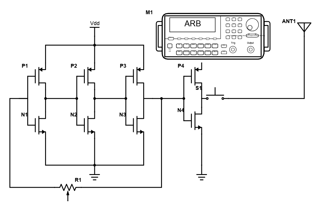
The schematic for the radio circuit is shown below.
Schematic Diagram

For Vdd, you can use a DC power supply at 10v. The key here is using an odd number of CMOS transistors for the oscillator. The ring oscillator (P1 & N1, P2 & N2, P3 & N3) can be observed on the left side of the above diagram. Essentially, each CMOS transistor is a NOT gate. When all three transistors are on, based on the delay, one transistor will produce an output at its gate. This will drive the output of the adjacent transistor. Likewise, it will start to flip the output of the subsequent transistor. Since, there are odd number of transistors the bit flip will occur in an oscillating manner continuously. The delay at each transistor will thus determine the frequency of the waveform generated. This will act as our carrier signal.
If you need to adjust the frequency of the carrier signal, you can add a resistor between each of the two transistors. Also, you can connect a capacitor between the output and the ground. By doing so, you will modify the RC time constant and this will determine the delay between two transistors. To generate a carrier signal in the range of 530 – 550 kHz, a 50k post variable resistor should be enough (included between the first and the last CMOS transistor).
Generating a Signal
Now, we need an information signal. The signal is fed through a function generator. We can use a square waveform with a 1 kHz frequency and a DC offset of 1.8v and amplitude from 0 to 5v. Ensure to enable high impedance mode on the function generator. You can also use an oscilloscope to view the function generated and fed in to the circuit. The output of the function generator is connected to the VDD of the fourth CMOS transistor. The last transistor acts as a buffer and prevents the antenna from changing the RC constant of the ring oscillator.
For the antenna, you can select a wire of around length 5 – 6 inches. After you power up the system, you should be able to hear a high frequency sound when you tap on the push button (you will also need to tune your AM radio to the proper frequency). This step will need some patience and start from the lower end. If you’re using a 50k pot resistor and at a room temperature of around 68 F, the tune in frequency should be around 530 – 550 kHz.
Transmitting the Morse Code
By clicking on the push button at predetermined time intervals, you can send information in terms of a morse code.